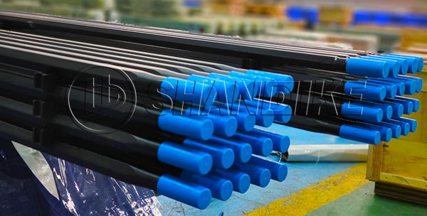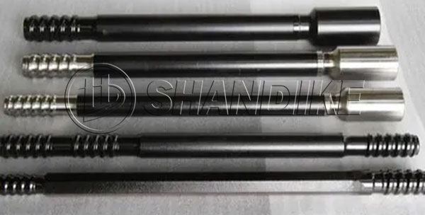

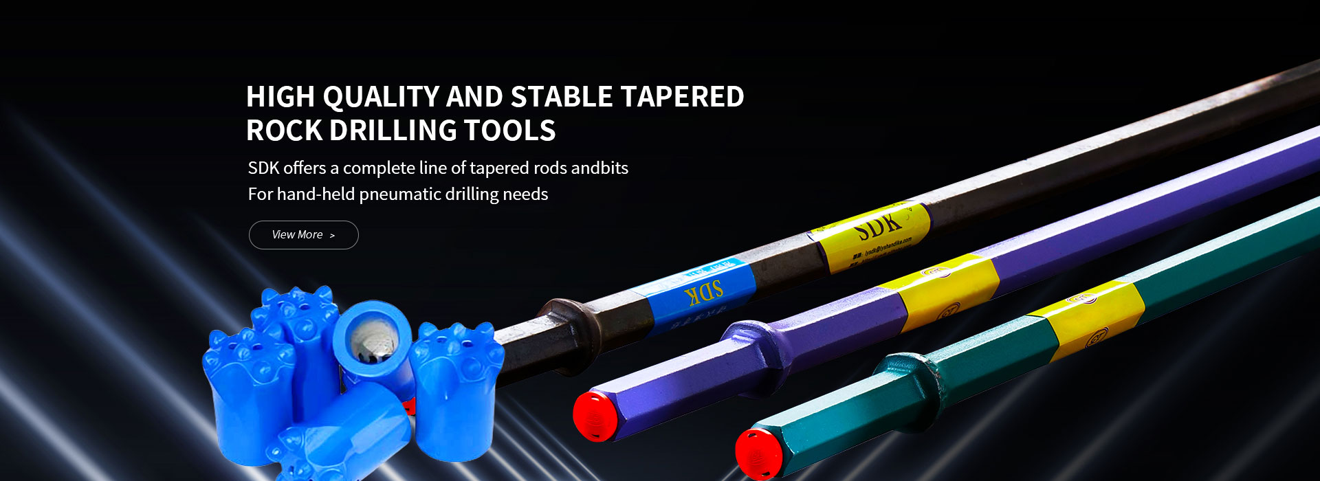
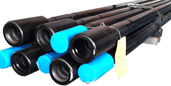
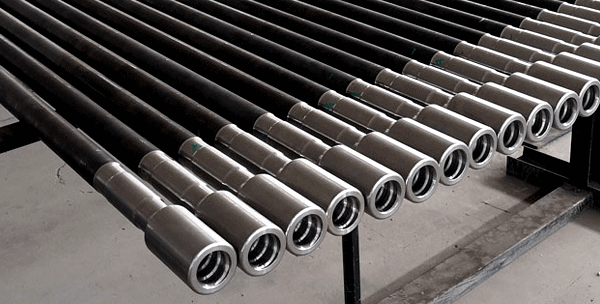
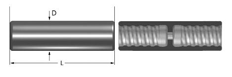
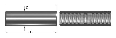
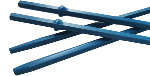
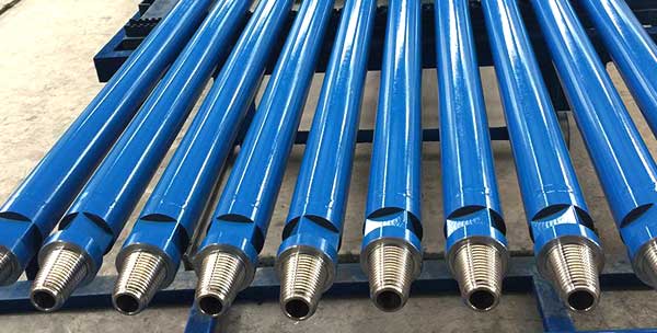
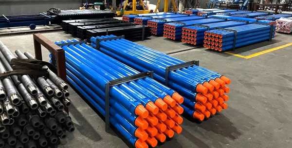
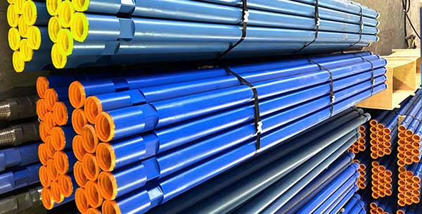
MF rod, also known as speed drill rod, has a male thread at one end and a female thread at the other end. It can directly connect to the shank adapter without the aid of a coupling sleeve, which eliminates the defect that the equal diameter thread connection is prone to vibration. The quick-change properties of male/female rods improve the overall drilling efficiency.
As an MF Rod manufacturer, we have two MF rod factories in China. Our MF drill rods are made of high-quality alloy steel and advanced thread manufacturing technology, and have excellent performance in wear resistance and flexibility. We offer speed drill rods with various threads, such as R23 MF drill rod, R32 MF drill rod, R38 MF rod, T35 MF rod, T38 MF drill rod, T45 MF rod, MF rod T51, GT60 MF drill rod, SR35 speed rod, etc.
23CrNi3Mo is used for Extension rods, MF-rods, Coupling, Shank adapter etc.
| C | Si | Mn | Cr | Mo | Ni | V | P | S | Cu |
| 0.19~0.27 | 0.15~0.40 | 0.50~0.80 | 1.15~1.45 | 0.15~0.40 | 2.70~3.10 | _ | ≤0.025 | ≤0.025 | ≤0.25 |
| Rod body diameter(mm) | ||||
| Length(mm) | D32 | D38 | D45 | D51 |
| ≤1000 | R32-Round 32-R32-L MF R32-Round 32-R32-L | T38-Round 39-T38-L MF T38-Round 39-T38-L R38-Round 39-R38-L MF R38-Round 39-R38-L | T45-Round 46-T45-L MF T45-Round 46-T45-L | T51-Round 52-T51-L MF T51-Round 52-T51-L |
| 1220 | ||||
| 1525 | ||||
| 1830 | ||||
| 2500(2475) | ||||
| 2800(2900) | ||||
| 3000(3050)(3090) | ||||
| 3660(3700) | ||||
| 4000 | ||||
| 4270(4305) | ||||
| 4700 | ||||
| 4915 | ||||
| 5100 | ||||
| 5525 | ||||
| 6100 | ||||
| 6400 | ||||
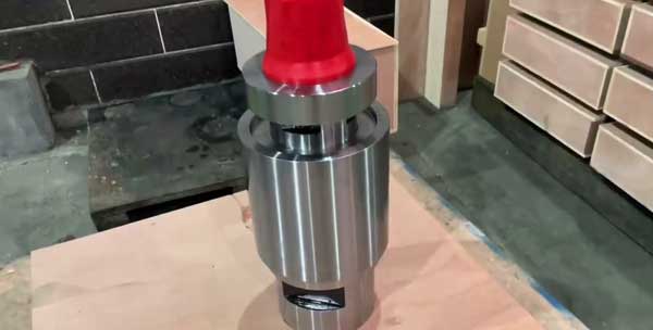
Drill Rod Coupling Sleeve is a sleeve-shaped rock drilling component with internal threads for connecting shank adapter and drill rod, or drill rod and drill rod. We produce and provide three types of drill rod couplings – semi bridge couplings, full bridge couplings, and crossover couplings, which can meet the requirements of all applications.
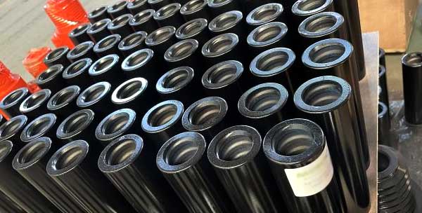
Standard coupling sleeve, also known as semi bridge coupling sleeve, has a section of the bridge without a thread in the middle. The threaded part of the drill pipe cannot be screwed through the bridge part of the coupling, and the end of the thread can closely adhere to the casing bridge zone. Standard coupling sleeve is particularly suitable for high-torque drilling rigs. Most rope thread (R thread) and trapezoidal thread (T thread) coupling sleeves are with half-bridge type. The half-bridge type is by far the most widely used couplings.
Full bridge coupling sleeve can completely eliminate the looseness of the coupling sleeves along with the threaded connection. It is mainly used in surface mining, with better disassembly characteristics, firmer connections, and almost no clamping situation.

Crossover couplings are used to convert different thread types or thread diameter sizes.
| Coupling Sleeve | ||||
| Thread | Diameter | Length | ||
| mm | inch | mm | inch | |
| R25 | 35 | 1 19/50 | 150 | 5 9/10 |
| R28 | 40 | 1 29/50 | 155 | 6 1/10 |
| R32 | 45 | 1 3/4 | 170 | 6 57/64 |
| R38 | 55 | 2 5/32 | 170 | 6 57/64 |
| T38 | 55 | 2 5/32 | 190 | 7 33/64 |
| T45 | 63 | 2 15/32 | 210 | 8 17/64 |
| T45 | 66 | 2 19/32 | 210 | 8 17/64 |
| T51 | 72 | 2 7/8 | 235 | 9 1/4 |
| T51 | 76 | 3 | 235 | 9 1/4 |
| Adapter Coupling / Crossover Coupling | |||||
| Thread | Diameter | Length | |||
| A | B | mm | inch | mm | inch |
| R25 | R32 | 45 | 1 3/4 | 170 | 6 57/64 |
| R28 | R32 | 45 | 1 3/4 | 170 | 6 57/64 |
| R32 | R38 | 55 | 2 5/32 | 180 | 7 1/8 |
| R32 | T38 | 55 | 2 5/32 | 180 | 7 1/8 |
| R38 | T38 | 55 | 2 5/32 | 190 | 7 33/64 |
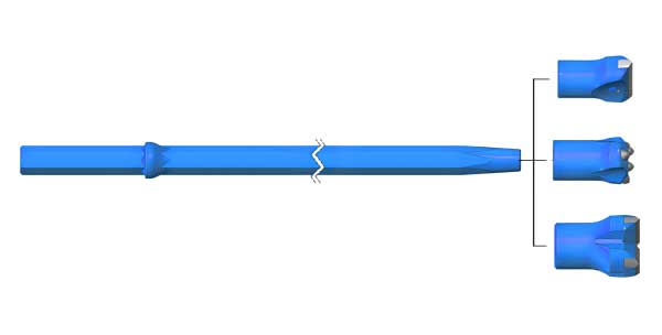
Tapered drill rod effective lengths are measured from the collar to the bit end, which are usually from 0.6meter to 3.6 meters.
Parameters
Shank sizes: Hex.19mm, Hex. 22mm, Hex.25mm
Taper degrees: 7°, 11°, 12°.
Length: 400 – 8000mm.
Specifications:
Drilling duties in tunneling, construction, mining, quarrying, etc.
| 22mm(7/8″)Tapered drill rods | L | Taper Degree | Weight (kg) | |
| mm | foot/inch | |||
H22×108 Shank  | 500 | 1′ 5/8″ | 7o | 1.5 |
| 800 | 2′7 1/2″ | 2.4 | ||
| 1000 | 3′3 3/8″ | 3 | ||
| 1200 | 3′11 1/4″ | 3.6 | ||
| 1500 | 4′ 11″ | 4.5 | ||
| 1800 | 5′10 7/8″ | 5.5 | ||
| 2000 | 6′6 3/4″ | 6.1 | ||
| 2200 | 7′2 5/8″ | 6.7 | ||
| 2500 | 8′2 3/8″ | 7.6 | ||
| 3000 | 9′10 1/8″ | 9.1 | ||
| 3500 | 11′5 3/4″ | 10.6 | ||
| 4000 | 13′1 1/2″ | 12.1 | ||
| 4500 | 14′9 1/8″ | 13.6 | ||
| 5000 | 16′4 5/8″ | 15.1 | ||
| 6000 | 19′8 1/4″ | 18.2 | ||
| 7000 | 22′11 5/8″ | 21.2 | ||
| 8000 | 26′ 3″ | 24.2 | ||
H22×108 Shank | 800 | 2′7 1/2″ | 12o | 2.4 |
| 1200 | 3′11 1/4″ | 3.6 | ||
| 1600 | 5′ 3″ | 4.9 | ||
| 2200 | 7′2 5/8″ | 6.7 | ||
| 2400 | 7′10 1/2″ | 7.3 | ||
| 3200 | 10′ 6″ | 9.7 | ||
H22×108 Shank | 1800 | 5′10 7/8″ | 7o | 5.5 |
| 2000 | 6′6 3/4″ | 6.1 | ||
| 2500 | 8′2 3/8″ | 7.6 | ||
| 3000 | 9′10 1/8″ | 9.1 | ||
| 3500 | 11′5 3/4″ | 10.6 | ||
| 4000 | 13′1 1/2″ | 12.1 | ||
| 5000 | 16′4 5/8″ | 15.1 | ||
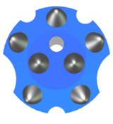
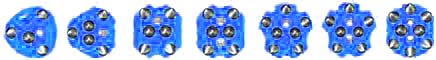
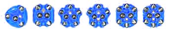
Taper bits, especially Tapered button bits are the most popular tapered drill bits with a wide selection of head diameters from 26mm to 48mm. With carbide buttons hot pressed on the bit skirts, tapered button bits have a good drilling performance and are excellent in longevity.

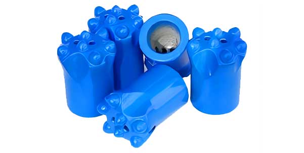
Taper drill bits are connected to taper drill rods for drilling duties, suitable for tunneling, construction, mining, quarrying, etc.
 |  |  |
| Chisel Taper Bit | Cross Taper Bit | Button Taper Bit |
 | Taper Chisel Bits Taper Degree: 4°46′, 6°, 7° Diameter: 26-43mm |
 | Taper Cross Bits Taper Degree: 4°46′, 6°, 7°, 11°, 12° Diameter: 32-46mm |
 | 4° 46′ Taper Button Bits Taper Degree: 4°46′ Diameter: 36-43mm |
 | 7° Taper Button Bits Taper Degree: 7° Diameter: 32-41mm |
 | 11° Taper Button Bits Taper Degree: 11° Diameter: 32-41mm |
 | 12° Taper Button Bits Taper Degree: 12° Diameter: 30-42mm |
Fully-carburized Taper Drill Rod is to increase the surface carbon content of the drill rod through the carburization craft, level up the surface hardness and the overall strength, and increase the service life of the taper drill rod. Compared with the conventional taper drill rod, Fully-carburized Taper Drill Rod is high in strength and good in abrasive resistance. Under the same industrial and mining, the life of fully-carburized taper drill rods is times of that of the common taper drill rods.
Taper degree: 4°46’, 6°, 7°, 11°, 12°
Shank specification: Hex.19mm, Hex. 22mm, Hex.25mm
Besides the regular drill rod length, our company can customize the product length according to the needs of the client.

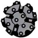
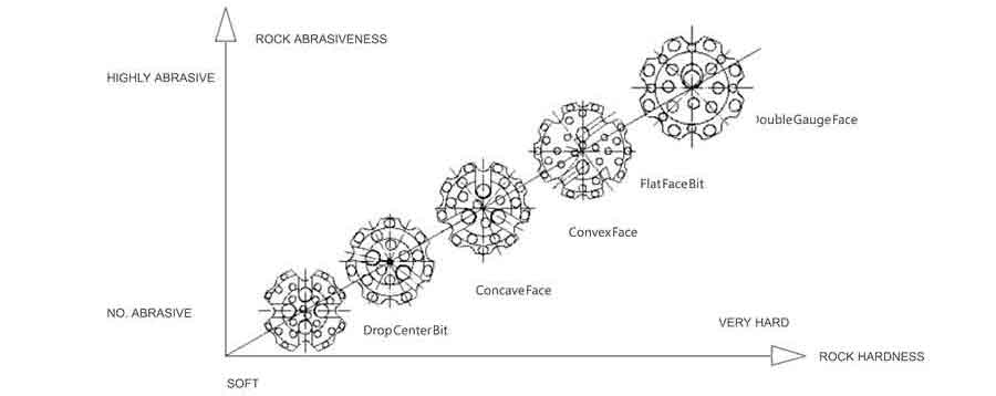
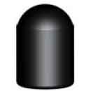
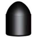
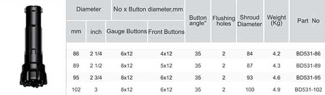
SHANDIKE has a comprehensive range of DTH drill bits to match all conceivable applications. Each bit is made from quality alloy steel, and has been precision machined to produce a perfect body, heat treated to the required hardness, given surface compression for fatigue resistance, and fitted with precision buttons manufactured in-house. These are deigned for specific applications for all rock types, hardness’s and condition. Bit life and rate of penetration are the most important criteria in selecting the right bit for a particular application.
 | Drop Center For high penetration rates in soft to medium hard and fissured rock formations.Low tomedium air pressures.Maximum hole deviation control. |
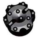 | Concave Face The all-round application bit face specifically for medium hard and homogenerous rockformations.Good hole deviation control and good flushing capacity. |
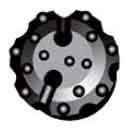 | Convex Face For high penetration rates in soft to medium-hard with low to medium air pressures.It isthe most resistance to steel wash,and may reduce the load and wear on the gaugebuttons,but poor hole deviation control. |
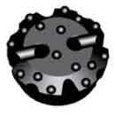 | Double Gauge Face This kind of face shape is suitable for fast penetration rates in medium to hard rockformations.Designed for high air pressures and good resistance to steel wash step gaugebit. |
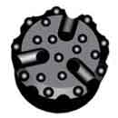 | Flat Face The Pineapple Bit can be dressed with ballistic buttons for use in soft to medium hard |
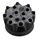 | Pineapple Face The Pineapple Bit can be dressed with ballistic buttons for use in soft to medium hardformations where fractured rock can be expected,or can be supplied with spherical buttonsfor hard and abrasive formations. |
 |  |  |  |  |
| Round Button | Semi-Ballistic Buttons | Ballistic Button | Flat Button | Sharp Button |
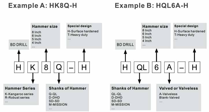
Product codes are a valuable tool to describe and identify the product. In the code structure we have tried to describe the product features with an alphanumeric system and not always 100% logical, but with the attached key you will be able to find the product you are looking for or alternative products.
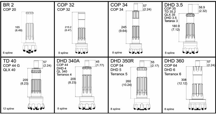
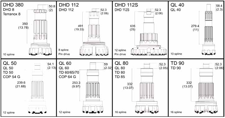
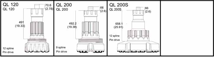
| Specification of dth hammer button bits: | Diameter: (mm) |
| 1-2 inch low air pressure DTH bits Shank: BR1, BR2, DHD2.5 | 57/64/70/76/80/82/90 |
| 3 inch high Air pressure DHT bits Shank: BR3,DHD3.5,COP34,COP32,QL30,M30,IR3.5 | 85 / 90 / 95 / 100 / 105/110 |
| 4 inch high Air pressure DHT bits Shank:DHD340,COP44,M40,SD4,QL40 | 105 / 110 / 115 / 120 / 127/130 |
| 5 inch high Air pressure DHT bits Shank:DHD350,COP54,M50,SD5,QL50 | 133 / 140 / 146 / 152 / 165 |
| 6 inch high Air pressure DHT bits Shank:DHD360,M60,SD6,QL60,COP64 | 152 / 165 / 178 / 190 / 203 |
| 8 inch high Air pressure DHT bits Shank:DHD380,COP84,M80,SD8,QL80 | 195 / 203 / 216 / 254 / 305 |
| 10 inch high Air pressure DTH bits Shank:SD10, NUMA100 | 254/270/279/295/305 |
| 12 inch high Air pressure DTH bits Shank:SD12,DHD1120,NUMA120,NUMA125 | 305/330/343/356/368/381 |
The optimum range of hole size for blast hole drilling with DTH is 90 mm to 254 mm (3 ½”–10″). Smaller blast holes are generally drilled using tophammer, and larger holes generally use rotary machines.
In other applications, like foundation drilling, DTH hammers can be used with single bit in hole sizes up to . 750 mm (30″). With multiple hammer units CD (Cluster drills) drill holes up to 70″ or 1778 mm.
As a rule of thumb, the smallest hole diameter a DTH hammer can drill is its nominal size. A 4 inch hammer will drill a 4 inch (102 mm) hole. The limiting factor is the outside diameter of the hammer, because, as hole diameter reduces, airflow is restricted. Maximum hole size for production drilling is the nominal hammer size plus 1 inch, so for a 4 inch hammer the maximum hole size is 5 inch (127–130 mm).
Choosing the right hammer is largely determined by hole size and type of rock formation. Ideally, the size of the hammer should match the required hole dimension as closely as possible, leaving just enough space for cuttings to evacuate the hole.
Product codes are a valuable tool to describe and identify the product. In the code structure we have tried to describe the product features with an alphanumeric system and not always 100% logical, but with the attached key you will be able to find the product you are looking for or alternative products.
| Hammer | BR2A | DHD3.5 | HK4D | HD45 | HQL4A | HQL50 | HK5Q | HD55 | HQL60 | HQL6A | HQL80 | HD85 | HK9Q | HSD10 | HSD12 | HK12Y | N125-R |
|---|---|---|---|---|---|---|---|---|---|---|---|---|---|---|---|---|---|
| Recommended bit size, mm | 76 | 92-105 | 112-127 | 140-152 | 165-178 | 203-229 | 216-229 | 245-305 | 305-445 | 305-350 | 305-445 | ||||||
| Bit Shank | BR2A | DHD3.5 | DHD340A | QL40 | QL50 | DHD350 | QL60 | QL80 | DHD380 | QL80 | SD10 | SD12 | HY12 | NUMA125R | |||
| External diameter, mm | 63 | 82 | 100 | 100 | 101 | 126.5 | 127.5 | 126.5 | 148 | 146 | 185 | 185 | 203 | 225 | 275 | 275 | 275 |
| Length excl. thread, mm (Less bit) | 837 | 855 | 915 | 1032.5 | 1057 | 1147 | 935 | 1167 | 1121 | 1182 | 1471 | 1487 | 1345 | 1413 | 1680 | 1590 | 1812 |
| Hammer weight, kg (Less bit) | 14.1 | 25 | 37.5 | 40.6 | 41 | 71.6 | 67.6 | 77.2 | 105 | 105 | 203 | 206 | 228 | 303 | 526 | 510.2 | 546 |
| Package case size | (L)910 (W)90 (H)120 | (L)1200 (W)110 (H)140 | (L)1010 (W)130 (H)160 | (L)1080 (W)125 (H)134 | (L)1150 (W)130 (H)160 | (L)1290 (W)150 (H)175 | (L)1100 (W)155 (H)180 | (L)1290 (W)150 (H)175 | (L)1270 (W)170 (H)200 | (L)1260 (W)180 (H)200 | (L)1440 (W)230 (H)270 | (L)1560 (W)230 (H)270 | (L)1500 (W)240 (H)280 | (L)1620 (W)275 (H)290 | (L)1880 (W)320 (H)320 | (L)1665 (W)320 (H)360 | (L)1880 (W)310 (H)310 |
| Top Sub thread | RD50 | 2-3/8″ API REG | 3-1/2″ API REG | 4-1/2″ API REG | 6-5/8″ API REG | 6-5/8″ API REG 7-5/8″ API REG | 6-5/8″ API REG | ||||||||||
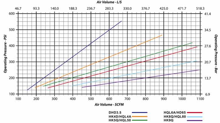
| Working Pressure, PSI | 80-170 | 150-250 | 200-300 | 250-350 | 300-350 | 300-380 | 300-380 | 150-350 | 200-350 | ||||||||
| Air consumption, CFM | 250-350 | 300-400 | 500-700 | 500-800 | 600-900 | 950-1200 | 950-1200 | 1000-1800 | 1200-1500 | 800-1800 | |||||||
| Piston diameter, mm | 42.7 | 65 | 82 | 80 | 80 | 104 | 102 | 100 | 122 | 121 | 150 | 150 | 165 | 185 | 225 | ||
| Piston weight, kg | 1.7 | 5.1 | 9.2 | 9 | 9 | 17 | 17 | 16 | 24 | 24 | 38 | 42 | 50 | 68 | 110 | 111 | 111 |
| Wrench flat, mm | L47 W50 | L57 W35 | L74.5 W45 | L64 W40 | NO wrench flat | L89 W60 | L88 W50 | L89 W60 | L101 W65 | L101 W60 | L128 W70 | L140 W70 | L128 W70 | L140 W70 | L140 W70 | L140 W70 | L140 L70 |
| Feed force, kN | 2~6 | 3~8 | 5~15 | 6~25 | 7~20 | 10~25 | 15~30 | 20~35 | |||||||||
| Rotation speed, r/min | 30-70 | 3-90 | 25-80 | 20-70 | 25-60 | 20-60 | 15-35 | ||||||||||
| Drilling conditions and project specifications may require larger air package to be used | |||||||||||||||||
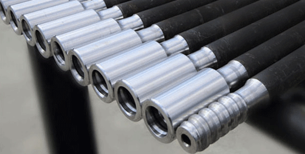
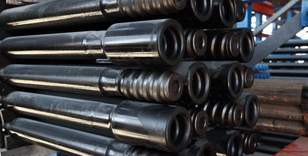
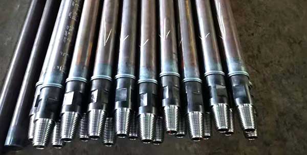
The DTH drill pipe consist of pipe and two adapters, box and pin. We use high strength and well-resistance alloy steel, inserting of high tensile seamless pipe, and according to different drilling depth, we can offer various thickness of pipe and material for customers’requirements.
DTH drill pipe Feature
• Diameter: 76mm, 89mm, 102mm, 114mm, 127mm, 140mm
• Length: 1000mm, 1500mm, 2000mm, 3000mm, 5000mm, 6000mm
• Thread: 2 3/8’’ API REG, 2 7/8’’ API REG, 3 1/2’’ API REG, 4 1/2’’ API REG,2 3/8″ API IF, 3 1/2″ API IF; BECO 6”, BECO 8”
• Wall thickness: 5.5mm/6.5mm/7.5mm/8.5mm/10mm
• Other spaecial size can be customized by customer’s drawing.
• Advanced heat treatment technology and friction welding mahcine.
| Rod dia | Rod length | Thickness | Connect thread | Wrench flats | |
| (inch) | (mm) | (mm) | (mm) | (mm) | |
| 3 | 76 | 1000-6000 | 5 | API2 3/8”REG | 57/64.5 |
| 3 | 76 | 1000-9000 | 8 | API2 3/8”REG | 57/64.5 |
| 3 1/2 | 89 | 1000-6000 | 6 | API2 3/8”REG | 70/64 |
| 3 1/2 | 89 | 1000-9600 | 8 | API2 3/8”REG | 70/64 |
| 4 | 102 | 1000-9000 | 10 | API2 3/7”REG | 76/89 |
| 4 1/2 | 114 | 1500-7620 | 6 | API3 1/2”REG | 89/95 |
| 4 1/2 | 114 | 1500-9140 | 8 | API3 1/2”REG | 89/95 |
| 4 1/2 | 114 | 1500-9140 | 10 | API3 1/2”REG | 89/95 |
| 4 1/2 | 114 | 1500-9140 | 18 | API3 1/2”REG | 89/95 |
| 5 | 127 | 1500-9500 | 12 | API3 1/2”REG | 89 |
| 5 | 127 | 1500-9500 | 14 | API3 1/2”REG | 89 |
| 5 | 127 | 1500-9500 | 18 | API3 1/2”REG | 89 |
| 5 1/2 | 140 | 1500-9500 | 9 | API4 1/2”REG or 4’FH | 114 |
| 5 1/2 | 140 | 1500-9500 | 10 | API4 1/2”REG or 4’FH | 114 |
| 5 1/2 | 140 | 1500-9500 | 12 | API4 1/2”REG or 4’FH | 114 |
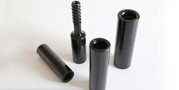
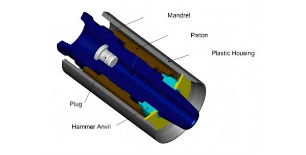
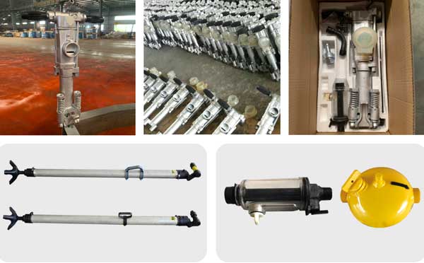
In case of jamming of any drilling tool in the boring process, the back hammer will assist you to solve the stuck problem by giving a backward impact power.
The back hammer may be mounted on the drill pipe joint between the borehole gripper and the swivel head, thus creating a combined effect of effective reverse impact and vibration.
The back hammer is consisted of three components and a plastic housing.
The housing acts both as an exhaust emissions guider and a muffler. With regards to the maintenance, it’s only necessary to keep it clean and the linking section we protected when the back hammer is not in use.
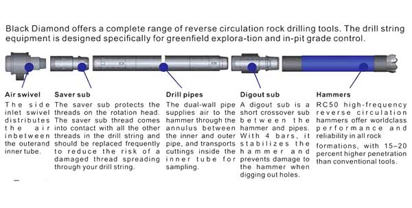
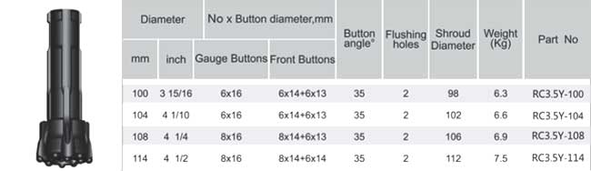
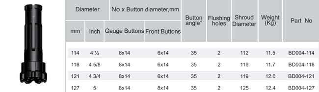
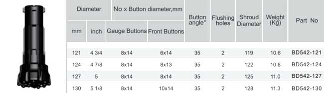
The reverse circulation hammer is used to collect underground rock and mineral samples quickly and efficiently using a pneumatic rotary drill. This hammer offers high speed and low cost per meter drilling. This type of drilling is considered ideal for obtaining mineral samples in the early phases of an exploration project. As all the rock cuttings in an RC hammer are recovered at the surface through the centre of the hammer and drill string, the samples collected through this method are uncontaminated. This hammer has also been designed to handle injection of water, foam, oil and polymers without any performance loss.
As all the rock cuttings in an RC hammer are recovered at the surface through the centre of the hammer and drill string, the samples collected through this method are uncontaminated. This hammer has also been designed to handle injection of water, foam, oil and polymers without any performance loss.
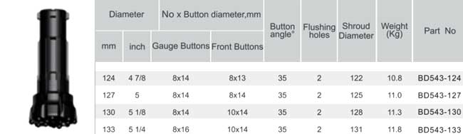
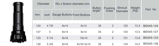
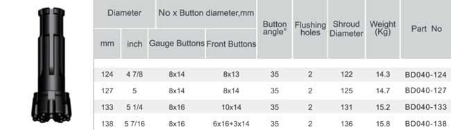
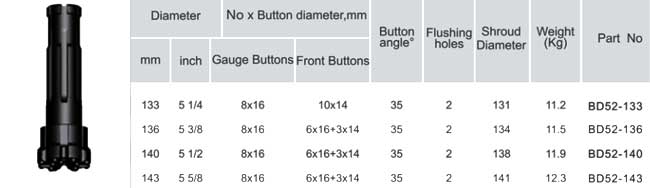
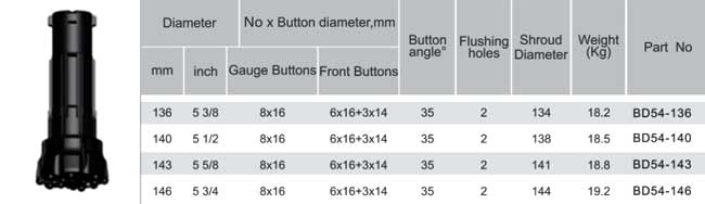
| Hammer | BD351 | RC3.5 | BD004 | BD542 | BD543 | BD545 | BD040 | BD52 | BD54 | A67 | |||||||||||
|---|---|---|---|---|---|---|---|---|---|---|---|---|---|---|---|---|---|---|---|---|---|
| Top sub thread | R3″ | R3″ | R3.5″ | R4″ | M4″ | R3.5″ | R4″ | M4″ | R4″ | M4″ | M4.5″ | R4.5″ | M4″ | R4″ | M4.5″ | R4.5″ | M4.5″ | R4.5″ | M4.5″ | R4.5″ | M4.5″ |
| Package case size, mm | (L)1100 (W)110 (H)120 | (L)1230 (W)120 (H)150 | (L)1300 (W)150 (H)180 | (L)1230 (W)140 (H)170 | (L)1260 (W)150 (H)180 | (L)1300 (W)150 (H)180 | (L)1300 (W)160 (H)190 | (L)1300 (W)160 (H)190 | (L)1330 (W)160 (H)190 | ||||||||||||
| Recommended bit size, mm | 86-100 | 100-110 | 111-125 | 113-133 | 123-140 | 127-140 | 133-143 | 136-146 | 136-146 | ||||||||||||
| Bit shank | RE351 | RC3.5 | RE004 | RE542 | RE543 | RE545 | RE040 | PR52 | PR54 | BD67 | |||||||||||
| External diameter, mm | 81 | 94 | 107 | 109.5 | 116 | 117.5 | 121 | 120.5 | 130 | 132 | |||||||||||
| Length excl. thread, mm (Less bit) | 1069 | 1184 | 1252 | 1191 | 1261 | 1210 | 1227 | 1294 | 1200 | ||||||||||||
| Hammer weight, kg (Less bit) | 29 | 44 | 52 | 57 | 63 | 65 | 53.8 | 47.5 | 69.4 | 69.4 | 68.5 | 84.5 | 81.8 | ||||||||
| Piston weight, kg | 4.8 | 8.3 | 10.5 | 11.6 | 11.6 | 13.5 | 13.6 | 14.3 | 17 | 17 | |||||||||||
| Wrench flat, mm | No Wrench Flat | (L)82 (W)40 | (L)90 (W)45 | (L)90 (W)45 | (L)90 (W)45 | (L)95 (W)45 | (L)95 (W)45 | (L)95 (W)50 | (L)95 (W)45 | (L)95 (W)50 | (L)102 (W)50 | (L)102 (W)50 | (L)94 (W)50 | (L)94 (W)50 | (L)94 (W)50 | (L)94 (W)50 | (L)94 (W)50 | (L)94 (W)50 | (L)100 (W)50 | (L)100 (W)50 | (L)95 (W)51 |
| Drilling conditions and project specifications may require larger air packages to be used | |||||||||||||||||||||
RC series reverse circulation DTH Hammer is the latest developed product of our company. It is mainly used for deep exploration drilling and stope ore grade control.
It has the following characteristics:
1. Based on previous experience of ordinary hammers, combined with the features of reverse circulation hammer, optimized internal structure and ideal energy transfer, thus ensuring the series of hammers drilling with fast smooth and continuous sampling.
2. The internal structure is very simple with components of high rigidity, thus ensuring long life and easy maintenance of the hammer.
3. The collection tube adopts an integrative design and can be replaced without disassembling the hammer. With carburizing treatment, it has good abrasive resistance.
4. Equipped with bits designed with patent. Simply by replacing the drill bit, the same hammer can drill holes of different sizes ensuring that the sample is not contaminated.
5. In difficult condition such as loose soil, hard rock and plenty of water exists, sampling can be done well.
RC drilling, referred to as “ Centre Sample Recovery” or “Dual Wall Drilling”, employs a Dual Wall pipe where the drilling medium, normally high pressure air, is the passed between the outer and inner tubes down to the face of the drilling bit where it is returned up the centre tube along with the sample cut by the drill bit.
1. No contamination
The RC system collects sample through the recovery holes in the face of the drill bit immediately as the cuttings or sample is formed. The drilled sample does not have to travel the length of the hammer where contamination and loss of sample takes place.
2. Higher Production
In broken and fractured ground conditions, the RC has more higher penetration rates than the conventional hammer.
3. Dry Sample
Even in certain water bearing strata, it is still possible to collect a dry sample because the cuttings are collected as they are formed through the face of the drill bit.
4. Higher Sample Recovery
Because the sample is collected through the face of the drill bit, there is no loss of sample when drilling through broken or fractured ground. And since the bit matched to the chuck size, there is very little bypass of sample and recovery rates of up to 98% are generally achievable.
The RC bits are the tool cutting rock. Shandike RC DTH bits are made of superior quality alloy steel and T.C carbides.
Shandike GSE DHD DTH Hammers
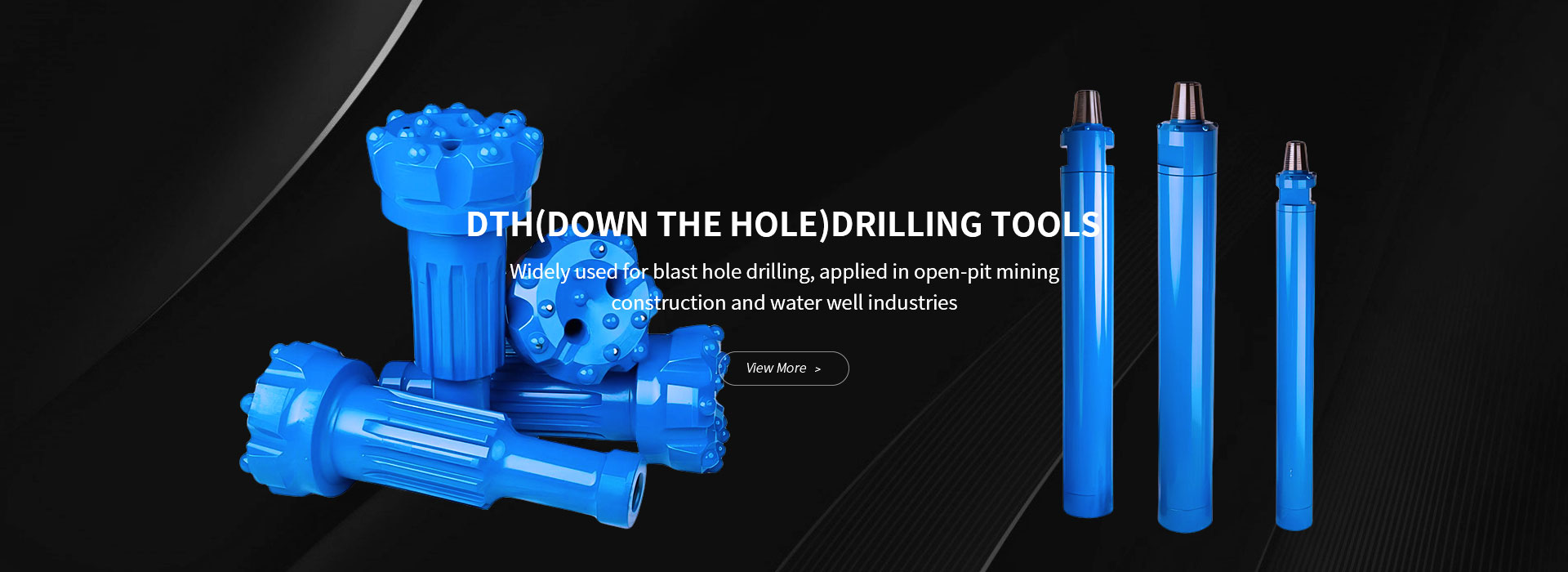
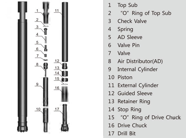
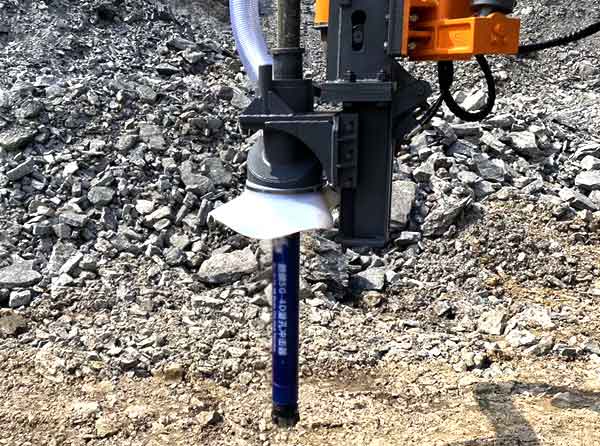
DTH (down-the-hole) drilling involves a drilling hammer at the bottom of a drill string, the hammer is powered by compressed air transmitted via drilling rod to drive piston and produce impact power, which is then delivered into rocks for drilling and crushing. DTH drilling can be applied in mining, quarrying, water well drilling, foundation piling, etc. DTH hammer uses compressed air to produce impact power, thus to drive drill bits to crush rocks.
• Premium material, fine CNC and heat-treatment manufacturing processes and optimized design;
• Good stability and reliability;
• High impact frequency;
• Lowered compressed air consumption;
• Long lifespan
Mining, quarrying, water well drilling, geothermal well drilling, foundation piling, etc.
 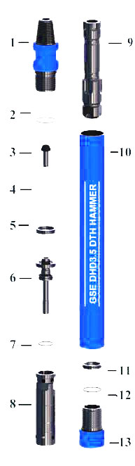 | 01 – Top Sub | 02 – O Ring | 03 – Check Valve | 04 – Spring |
| 05 – Steel Washer | 06 – Rigid Valve | 07 – O Ring | 08 – Internal Cylinder | |
| 09 – Pistion | 10 – Out Tube | 11 – Bit Retainer Ring | 12 – O Ring | |
| 13 – Drive Sub |
GSE-DHD3.5 DTH Hammer
| Net Weight | Out Diameter | GSE DHD3.5 DTH Hammer Length With Out Bits | Frequency at 18 Bar | |
| 22.62 kgs | 80 mm | 808 mm | 32 Hz | |
| Rec. Hole Size | Working Pressure | Air Consumption: M3(CBM)/min | ||
| 90 mm-105 mm | 8 bar – 30 bar | @10 bar | @18 bar | @24 bar |
| 4.5 | 9.5 | 12.5 | ||
GSE-DHD340 DTH Hammer
| Net Weight | Out Diameter | GSE DHD340 DTH Hammer Length With Out Bits | Frequency at 18 Bar | |
| 38.00 kgs | 99 mm | 881 mm | 31 Hz | |
| Rec. Hole Size | Working Pressure | Air Consumption: M3(CBM)/min | ||
| 108mm – 130mm | 8 bar – 30 bar | @ 10 bar | @ 18 bar | @ 24 bar |
| 5 | 10.2 | 15 | ||
GSE-DHD350 DTH Hammer
| Net Weight | Out Diameter | GSE DHD350 DTH Hammer Length With Out Bits | Frequency at 18 Bar | |
| 74.0 kgs | 126 mm | 1028 mm | 30 Hz | |
| Rec. Hole Size | Working Pressure | Air Consumption: M3(CBM)/min | ||
| 134mm – 152mm | 8 bar – 30 bar | @ 10 bar | @ 18 bar | @ 24 bar |
| 7.5 | 14.7 | 19.5 | ||
GSE-DHD360 DTH Hammer
| Net Weight | Out Diameter | GSE DHD360 DTH Hammer Length With Out Bits | Frequency at 18 Bar | |
| 112 kgs | 144 mm | 1135 mm | 28 Hz | |
| Rec. Hole Size | Working Pressure | Air Consumption: M3(CBM)/min | ||
| 154mm – 254mm | 8 bar – 30 bar | @ 10 bar | @ 18 bar | @ 24 bar |
| 8.7 | 14.5 | 25 | ||
GSE-DHD380 DTH Hammer
| Net Weight | Out Diameter | GSE DHD 380 DTH Hammer Length With Out Bits | Frequency at 18 Bar | |
| 180.0 kgs | 182 mm | 1228 mm | 23 Hz | |
| Rec. Hole Size | Working Pressure | Air Consumption: M3(CBM)/min | ||
| 203mm – 305mm | 8 bar – 30 bar | @ 10 bar | @ 18 bar | @ 24 bar |
| 12 | 26 | 35 | ||
Casing drilling, or casing while drilling (CWD) process, is a concept that combining two time-consuming processes, drilling and casing together, performing them at the same time. During the CWD process, powered by DTH hammer, a central piloting bit drives a ring bit to drill a hole wide enough for a casing tube to slide down, drilling and casing processes are therefore performed at the same time.
Eccentric is the most economical solutions because its ingenious reaming wing the bit is retrievable can be used at the next hole. This is particularly design for shallow holes, as is often the case in water well drilling, geothermal wells and for shallow micro-piling work. Odex is ideal for short holes in consolidated overburden. The component of Eccentric system consists of Pilot bits, Reamer bits, Guide device and casing shoe.
When drilling, the reamer bit will rotate out to enlarge the hole which enough for the casing tube slide down behind the reamer. When reached required depth, the drill pipe will drill to the reverse direction and the reamer bit will retract, it is allowing the whole drilling system to pass through the casing.
• Complete types of drilling tools suitable for casing tubes with various diameters;
• Good stability and reliability granted by premium alloy steel material and fine CNC manufacturing process;
• Cost-effectiveness realized by mass production.
Water well drilling, geothermal well drilling, foundation piling, geological prospecting, etc.
Structure
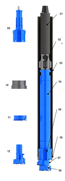 | 01 – Drill Pipe | 02 – Guide Sleeve | 03 – Steel Casing |
| 04 – DTH Hammer | 05 – Guide Device | 06 – Casing Shoe | |
| 07 – Reammer | 08 – Pilot Bit | 09- Guide Device | |
| 10 – Casing Shoe | 11 – Reammer | 12 – Pilot bit |
GSE-EDS82 Eccentric Drilling System (ODEX82)
| GSE-EDS82 Eccentric Drilling System (ODEX82) shank for IR3.5 DTH Hammer (other shanks are optional) | |
| Alternative casings may by used: | |
| Maximum outside diameter (mm) | 108 |
| Minimum inside diameter (mm) | 96 |
| Wall thickness (mm) | 6 |
GSE-EDS90 Eccentric Drilling System (ODEX90)
| GSE-EDS90 Eccentric Drilling System (ODEX90) shank for DHD3.5 DTH Hammer (others are optional) | |
| Alternative casings may be used: | |
| Maximum outside diameter (mm) | 115 |
| Minimum inside diameter (mm) | 102 |
| Wall thickness (mm) | 6 |
GSE-EDS115A Eccentric Drilling System (ODEX115A)
| GSE-EDS115A Eccentric Drilling System (ODEX115A) Shank for IR DHD340A DTH Hammer (others are optional) | |
| Alternative casings may be used: | |
| Maximum outside diameter (mm) | 142 |
| Minimum inside diameter (mm) | 128 |
| Wall thickness (mm) | 7 |
GSE-EDS115B Eccentric Drilling System (ODEX115B)
| GSE-EDS115B Eccentric Drilling System (ODEX115B) Shank for DHD340 DTH Hammer (others are optional) | |
| Alternative casings may be used: | |
| Manximum outside diameter (mm) | 146 |
| Minimum inside diameter (mm) | 130 |
| Wall thickness (mm) | 8 |
GSE-EDS140 Eccentric Drilling System (ODEX140)
| GSE-EDS140 Eccentric Drilling System (ODEX140) Shank for IR DHD350R DTH Hammer (others are optional) | |
| Alternative casings may be used: | |
| Maximum outside diameter (mm) | 168 |
| Minimum inside diameter (mm) | 152 |
| Wall thckness (mm) | 8 |
GSE-EDS145 Eccentric Drilling System (ODEX145)
| GSE-EDS145 Eccentric Drilling System (ODEX145) Shank for IR DHD350R DTH Hammer (others are optional) | |
| Alternative casings may be used: | |
| Maximum outside diameter (mm) | 178 |
| Minimum inside diameter (mm) | 158 |
| Wall thickness (mm) | 9 |
GSE-EDS147 Eccentric Drilling System (ODEX147)
| GSE-EDS147 Eccentric Drilling System (ODEX147) Shank for IR DHD350R DTH Hammer (others are optional) | |
| Alternative casing may be used: | |
| Maximum outside diameter (mm) | 183 |
| Minimum inside diameter (mm) | 163 |
| Wall thickness (mm) | 10 |
GSE-EDS165 Eccentric Drilling System (ODEX165)
| GSE-EDS165 Eccentric Drilling System (ODEX165) Shank for IR DHD360 DTH Hammer (others are optional) | |
| Alternative casings may be used: | |
| Maximum outside diameter (mm) | 195 |
| Minimum inside diameter (mm) | 182 |
| Wall thickness (mm) | 6.5 |
GSE-EDS180 Eccentric Drilling System (ODEX180)
| GSE-ED180 Eccentric Drilling System (ODEX180) Shank for DHD360, COP64, SD6 DTH Hammer | |
| Alternative casing may be used: | |
| Maximum outside diameter (mm) | 219 |
| Minimum inside diameter (mm) | 194 |
| Wall thickness (mm) | 12.5 |
GSE-EDS190 Eccentric Drilling System (ODEX190)
| GSE-EDS190 Eccentric Drilling System (ODEX190) Shank for IR DHD360 DTH Hammer (others are optional) | |
| Alternative casings may be used: | |
| Maximum outside diameter (mm) | 219 |
| Minimum inside diameter (mm) | 205 |
| Wall thickness (mm) | 7 |
GSE-EDS230 Eccentric Drilling System (ODEX230)
| GSE-EDS230 Eccentric Drilling System (ODEX230) Shank for IR DHD380 DTH Hammer (others are optional) | |
| Alternative casings may be used: | |
| Maximum outside diameter (mm) | 273 |
| Minimum inside diameter (mm) | 250 |
| Wall thickness (mm) | 11.5 |
GSE-EDS240 Eccentric Drilling System (ODEX240)
| GSE-EDS240 Eccentric Drilling System (ODEX240) Shank for IR DHD380 DTH Hammer (others are optional) | |
| Alternative casings may be used: | |
| Maximum outside diameter (mm) | 273 |
| Minimum inside diameter (mm) | 260 |
| Wall thickness (mm) | 6.5 |
Retrac button bits are mainly used in loose rock mass with relatively broken rock. The retrac skirt design can assist in retrieving the drill tool, reduce the phenomenon of bit stuck and buried, and help improve the straightness of the borehole.
As a China retrac button bit supplier, we can provide you with high-quality button bit includes retrac rock drill bits, such as R25 retract button bit, R28 retract button bit, R32 retrac button bit, R35 retrac button bit, R38 retrac button bit, T38 retract drill bit, T45 retract drill bit, T51 retract drill bit, GT60 retract button bit, ST58 retrac button bit, ST68 retrac button bit, SR35 retrac drill bit and other types of rock drill bit.
R25
| Appearance | Diameter | Buttons | Flushing Hole | Weight | Model No. | |||
[mm] | [in] | Gauge [No.] × [mm] | Front [No.] × [mm] | Side [No.] | Front [No.] | [kg] | ||
 | 41 | 1 5/8″ | 5 × 9 | 2 × 8 | 2 | 1 | 0.78 | R25-417YFP |
| 45 | 1 3/4″ | 6 × 9 | 3 × 8 | 1 | 3 | 1 | R25-459YFP | |
| 48 | 1 7/8″ | 6 × 10 | 3 × 9 | 1 | 3 | 1.1 | R25-489YFP | |
| 51 | 2″ | 6 × 10 | 3 × 9 | – | 3 | 1.35 | R25-519YFP | |
| 55 | 2 11/64″ | 6 × 11 | 3 × 9 | 1 | 3 | 1.54 | R25-559YFP | |
| 57 | 2 1/4″ | 6 × 10 | 3 × 10 | – | 3 | 1.6 | R25-579YFP | |
| 64 | 2 1/2″ | 8 × 11 | 4 × 10 | 1 | 2 | 2.2 | R25-6412YFP | |
R28
| Appearance | Diameter | Buttons | Flushing Hole | Weight | Model No. | |||
[mm] | [in] | Gauge [No.] × [mm] | Front [No.] × [mm] | Side [No.] | Front [No.] | [kg] | ||
| 45 | 1 3/4″ | 6 × 9 | 3 × 8 | 1 | 3 | 1 | R28-459YFP |
| 51 | 2″ | 6 × 10 | 3 × 9 | 1 | 3 | 1.35 | R28-519YFP | |
R32
| Appearance | Diameter | Buttons | Flushing Hole | Weight | Model No. | |||
[mm] | [in] | Gauge [No.] × [mm] | Front [No.] × [mm] | Side [No.] | Front [No.] | [kg] | ||
| 45 | 1 3/4″ | 6 × 9 | 3 × 8 | 1 | 3 | 0.9 | R32-459YFP |
| 48 | 1 7/8″ | 6 × 10 | 3 × 9 | 1 | 3 | 1.1 | R32-489YFP | |
| 51 | 2″ | 6 × 10 | 3 × 9 | – | 3 | 1.2 | R32-519YFP | |
| 57 | 2 1/4″ | 6 × 10 | 3 × 10 | – | 3 | 1.7 | R32-579YFP | |
| 64 | 2 1/2″ | 6 × 11 | 3 × 10 | 1 | 2 | 2.2 | R32-649YFP | |
 | 60 | 2 23/64″ | 8 × 10 | 4 × 9 | 1 | 2 | 1.7 | R32-6012YFP |
| 64 | 2 1/2″ | 8 × 10 | 4 × 10 | 2 | 2 | 1.9 | R32-6412YFP | |
| 76 | 3″ | 8 × 12 | 4 × 11 | 2 | 2 | 2.2 | R32-7612YFP | |
 | 76 | 3″ | 8 × 11 | 4 × 11, 1 × 11 | – | 4 | 3.3 | R32-7613YFA |
SR35
| Appearance | Diameter | Buttons | Flushing Hole | Weight | Model No. | |||
[mm] | [in] | Gauge [No.] × [mm] | Front [No.] × [mm] | Side [No.] | Front [No.] | [kg] | ||
| 51 | 2″ | 8 × 9 | 3 × 9 | 2 | 1 | 1.6 | SR35-5111YFP |
| 54 | 2 1/8″ | 8 × 9 | 3 × 9 | 2 | 1 | 1.8 | SR35-5411YFP | |
| 54 | 2 1/8″ | 6 × 10 | 3 × 9 | 1 | 3 | 1.3 | SR35-549YFA |
R38
| Appearance | Diameter | Buttons | Flushing Hole | Weight | Model No. | |||
[mm] | [in] | Gauge [No.] × [mm] | Front [No.] × [mm] | Side [No.] | Front [No.] | [kg] | ||
 | 64 | 2 1/2″ | 8 × 10 | 4 × 10 | 2 | 2 | 1.9 | R38-6412YFP |
| 76 | 3″ | 8 × 12 | 4 × 11 | 2 | 2 | 2.2 | R38-7612YFP | |
| 64 | 2 1/2″ | 6 × 11 | 3 × 10 | 1 | 2 | 1.9 | R38-649YFP | |
 | 64 | 2 1/2″ | 6 × 11 | 3 × 10, 1 × 9 | 1 | 2 | 1.9 | R38-6410YFA |
| 64 | 2 1/2″ | 8 × 10 | 4 × 10, 1 × 9 | 1 | 4 | 1.9 | R38-6413YFA | |
| 66 | 2 19/32″ | 6 × 11 | 3 × 10, 1 × 9 | 1 | 2 | 1.9 | R38-6610YFA | |
| 70 | 2 3/4″ | 8 × 10 | 4 × 10, 1 × 9 | 1 | 4 | 2.4 | R38-7013YFA | |
| 76 | 3″ | 8 × 11 | 4 × 11, 1 × 11 | – | 4 | 3.3 | R38-7613YFA | |
| 89 | 3 1/2″ | 8 × 12 | 4 × 12, 2 × 10 | 1 | 4 | 5.3 | R38-8914YFA | |
| 89 | 3 1/2″ | 8 × 12 | 4 × 11, 1 × 11 | 1 | 4 | 5.3 | R38-8913YFA | |
T38
| Appearance | Diameter | Buttons | Flushing Hole | Weight | Model No. | |||
[mm] | [in] | Gauge [No.] × [mm] | Front [No.] × [mm] | Side [No.] | Front [No.] | [kg] | ||
 | 64 | 2 1/2″ | 8 × 10 | 4 × 10 | 2 | 2 | 1.9 | T38-6412YFP |
| 76 | 3″ | 8 × 12 | 4 × 11 | 2 | 2 | 2.2 | T38-7612YFP | |
| 64 | 2 1/2″ | 6 × 11 | 3 × 10 | 1 | 2 | 1.9 | T38-649YFP | |
 | 64 | 2 1/2″ | 6 × 11 | 3 × 10, 1 × 9 | 1 | 2 | 1.9 | T38-6410YFA |
| 64 | 2 1/2″ | 8 × 10 | 4 × 10, 1 × 9 | 1 | 4 | 1.9 | T38-6413YFA | |
| 70 | 2 3/4″ | 8 × 10 | 4 × 10, 1 × 9 | 1 | 4 | 2.4 | T38-7013YFA | |
 | 65 | 2 9/16″ | 6 × 12 | 4 × 10 | 1 | 2 | 3.1 | T38-6510YSP |
T45
| Appearance | Diameter | Buttons | Flushing Hole | Weight | Model No. | |||
[mm] | [in] | Gauge [No.] × [mm] | Front [No.] × [mm] | Side [No.] | Front [No.] | [kg] | ||
 | 76 | 3″ | 8 × 12 | 4 × 11 | 2 | 2 | 2.2 | T45-7612YFP |
| 89 | 3 1/2″ | 8 × 13 | 5 × 12 | 2 | 2 | 5.2 | T45-8913YFP | |
| 102 | 4″ | 9 × 12 | 6 × 12 | – | 3 | 6.5 | T45-10215YFP | |
| 115 | 4 1/2″ | 9 × 14 | 7 × 13 | – | 3 | 10 | T45-11516YFP | |
| 115 | 4 1/2″ | 9 × 14 | 6 × 13 | – | 3 | 10 | T45-11515YFP | |
 | 76 | 3″ | 8 × 11 | 4 × 11, 1 × 11 | – | 4 | 3.2 | T45-7613YFA |
| 89 | 3 1/2″ | 8 × 12 | 4 × 12, 2 × 10 | 1 | 4 | 5.4 | T45-8914YFA | |
| 102 | 4″ | 8 × 12 | 4 × 12, 3 × 12 | – | 4 | 7.8 | T45-10215YFA | |
| 102 | 4″ | 8 × 13 | 4 × 12, 4 × 12 | – | 4 | 7.8 | T45-10216YFA | |
| 115 | 4 1/2″ | 8 × 14 | 4 × 13, 3 × 12 | – | 4 | 7.8 | T45-11515YFA | |
 | 76 | 3″ | 8 × 13 | 4 × 11, 1 × 11 | 1 | 4 | 3.5 | T45-7613YSA |
| 89 | 3 1/2″ | 8 × 12 | 4 × 12, 1 × 12 | 1 | 4 | 4.7 | T45-8913YSA | |
T51
| Appearance | Diameter | Buttons | Flushing Hole | Weight | Model No. | |||
[mm] | [in] | Gauge [No.] × [mm] | Front [No.] × [mm] | Side [No.] | Front [No.] | [kg] | ||
 | 89 | 3 1/2″ | 8 × 13 | 5 × 12 | 2 | 2 | 4.6 | T51-8913YFP |
| 102 | 4″ | 8 × 14 | 7 × 12 | 1 | 2 | 7.1 | T51-10215YFP | |
| 102 | 4″ | 9 × 12 | 6 × 12 | – | 3 | 7.1 | T51-10215YFP1 | |
| 115 | 4 1/2″ | 9 × 14 | 7 × 13 | – | 3 | 10 | T51-11516YFP | |
| 115 | 4 1/2″ | 9 × 14 | 6 × 13 | – | 3 | 10 | T51-11515YFP | |
| 127 | 5″ | 9 × 14 | 7 × 13 | – | 3 | 13 | T51-12716YFP | |
  | 89 | 3 1/2″ | 8 × 12 | 4 × 11, 1 × 11 | 1 | 4 | 5.3 | T51-8913YFA |
| 89 | 3 1/2″ | 8 × 12 | 4 × 12, 2 × 10 | 1 | 4 | 5.4 | T51-8914YFA | |
| 102 | 4″ | 8 × 12 | 4 × 12, 3 × 12 | – | 4 | 7.8 | T51-10215YFA | |
| 102 | 4″ | 8 × 13 | 4 × 12, 4 × 12 | – | 4 | 7.8 | T51-10216YFA | |
| 115 | 4 1/2″ | 8 × 14 | 4 × 13, 3 × 12 | – | 4 | 7.8 | T51-11515YFA | |
| 115 | 4 1/2″ | 8 × 14 | 4 × 14, 3 × 12 | – | 4 | 7.8 | T51-11515YFA1 | |
| 115 | 4 1/2″ | 8 × 14 | 4 × 14, 4 × 12 | – | 4 | 10 | T51-11516YFA | |
 | 89 | 3 1/2″ | 9 × 11 | 3 × 11, 2 × 10 | 1 | 3 | 4.8 | T51-8914YFA2 |
| 102 | 4″ | 9 × 12 | 3 × 12, 3 × 11 | 1 | 3 | 6.9 | T51-10215YFA1 | |
| 110 | 4 21/64″ | 9 × 14 | 6 × 12, 2 × 11 | – | 3 | 10 | T51-11017YFA | |
| 127 | 5″ | 8 × 16 | 4 × 14, 4 × 14 | – | 4 | 13.5 | T51-12716YFA | |
 | 102 | 4″ | 8 × 14 | 4 × 13, 1 × 13 | – | 2 | 10.1 | T51-10213YSA |
| 115 | 4 1/2″ | 9 × 14 | 6 × 12, 4 × 12 | – | 3 | 9.45 | T51-11519YSA | |
GT60
| Appearance | Diameter | Buttons | Flushing Hole | Weight | Model No. | |||
[mm] | [in] | Gauge [No.] × [mm] | Front [No.] × [mm] | Side [No.] | Front [No.] | [kg] | ||
 | 92 | 3 5/8″ | 9 × 12 | 9 × 12 | – | 2 | 5.1 | GT60-9218YSP |
| 96 | 3 25/32″ | 9 × 12 | 9 × 12 | – | 2 | 6.5 | GT60-9618YSP | |
| 102 | 4″ | 9 × 13 | 10 × 12 | – | 2 | 8.5 | GT60-10219YSP | |
 | 115 | 4 1/2″ | 9 × 14 | 10 × 12 | – | 3 | 10.8 | GT60-11519YSP |
| 127 | 5″ | 9 × 16 | 10 × 14 | – | 3 | 15 | GT60-12719YSP | |
| 140 | 5 1/2″ | 9 × 16 | 10 × 14 | – | 3 | 15 | GT60-14019YSP | |
| 152 | 6″ | 9 × 16 | 12 × 16 | – | 3 | 20 | GT60-15221YSP | |
 | 115 | 4 1/2″ | 9 × 16 | 6 × 13 | – | 3 | 15 | GT60-11515YSP |
ST58
| Appearance | Diameter | Buttons | Flushing Hole | Weight | Model No. | |||
[mm] | [in] | Gauge [No.] × [mm] | Front [No.] × [mm] | Side [No.] | Front [No.] | [kg] | ||
 | 89 | 3 1/2″ | 10 × 12 | 4 × 12, 2 × 12 | – | 4 | 5 | ST58-8916YSA |
| 115 | 4 1/2″ | 10 × 14 | 4 × 14, 4 × 14 | – | 4 | 10 | ST58-11518YSA | |
ST68
| Appearance | Diameter | Buttons | Flushing Hole | Weight | Model No. | |||
[mm] | [in] | Gauge [No.] × [mm] | Front [No.] × [mm] | Side [No.] | Front [No.] | [kg] | ||
 | 102 | 4″ | 10 × 12 | 4 × 12, 4 × 12 | – | 4 | 9.3 | ST68-10218YSA |
| 115 | 4 1/2″ | 10 × 14 | 4 × 14, 4 × 14 | – | 4 | 10 | ST68-11518YSA | |
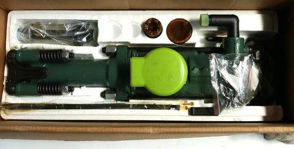
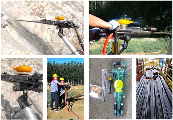
Hand-held Rock Drill is widely used for dry drilling in the medium-hard and hard rock. It is widely used in metallurgy, coal,railway, transportation, water conservancy construction and national defense stone works, etc. It is suitable for drilling andblasting under various of rocks at any direction angles.
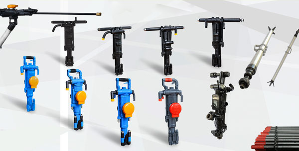
Advantage
Tapered drill rod,another name called taper rod, tapered drill steels, This provides a hexagonal chuck section to provide leverage for the rotation chuck bushing. It usually has a forged collar to maintain the proper shank striking face position in the rock drill, and a tapered bit end. Tapered steel lengths available from 0.6 mto 3.6 m in length—are measured from the collar to the bit end.
| Hand held rock drill specification | |||||
| Type | Y20LY | Y24 | Y26 | Y19A | TY24C |
| Weight(kg) | 18 | 23 | 26 | 19 | 23 |
| Shank size(mm) | 22*108 | 22*108 | 22*108 | 22*108 | 22*108 |
| Cylinder dia(mm) | 65 | 70 | 75 | 65 | 67 |
| Piston stroke(mm) | 60 | 70 | 70 | 54 | 70 |
| Working pressure(mpa) | 0.4 | 0.4-0.63 | 0.4-0.63 | 0.4-0.5 | 0.4-0.63 |
| Impact frequency(hz) | 28 | 28 | 28 | 28 | 28 |
| Air consumption | 25 | 55 | 47 | 37 | 55 |
| Air pipe inner dia(mm) | 19 | 19 | 19 | 19 | 19 |
| Rock drill hole dia(mm) | 30-45 | 30-45 | 30-45 | 30-45 | 30-45 |
| Rock drill hole depth(m) | 3 | 6 | 5 | 6 | 6 |
1、The height of the machine is moderate and the range of the stroke is large, so it can drill the anchor holes which are perpendicular to the roof surface, which solves the problem that the anchor holes in the roadway are not perpendicular to the surface of the roof for a long time, which guarantees the quality and progress of the project, saves the construction cost and improves the efficiency.
2、Good comprehensive rock drilling performance, not only for medium hard rock drilling, but also for rock drilling with f≤6, which can be applied to both rock roadway and quasi roadway.
3、Simple structure and more durable, easy to maintain, lower maintenance cost
4、Flexible start, air and water linkage, air leg fast return, air pressure adjustment and other institutions.
5、The control handle is concentrated with the shank body, the mechanism is novel and convenient to operate with the muffler cover can effectively reduce the noise and change the direction of the row of visits at will to improve the site The operation conditions of the field
6、YT28 rock drill is suitable for wet rock drilling of medium hard or hard rock.
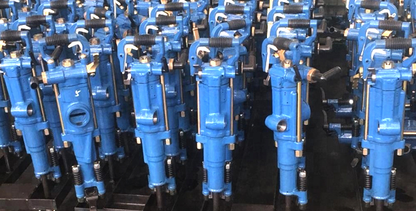
Tunneling and support in mining, transportation, water conservancy, hydropower and other projects. It is mainly used for quarries – dividing rocks.
| Weight | kg | 28 |
| Size | mm | 670 |
| Working pressure | Mpa | 0.5~0.63 |
| Piston diameter | mm | 80 |
| Piston stroke | mm | 60 |
| Air pipe inner diameter | mm | 25 |
| Water pipe inner diameter | mm | 13 |
| Drilling diameter | mm | 34~45 |
| Max drilling depth | m | 5 |
| Shank size | mm | H22×108 |
| Impact frequency | Hz | ≥37 |
| Impact energy | J | ≥70 |
| Air consumption | L/s | ≤81.6 |