Instructions for using YN27C gasoline rock drill machine Shandike
Detailed instructions on the technical specifications, operating methods, maintenance, troubleshooting, and other aspects of YN 27 and YN 27C internal combustion rock drills. The document first introduces the basic structure and working principle of the rock drill, and then elaborates in detail on the preparation work before operation, start-up, rock drilling, tool replacement, parking, impact operation, and operating precautions. In addition, specific steps and troubleshooting methods for maintenance, inspection, and adjustment work are provided.

| 1.Weight of main machine: | 27kg |
| 2.0verall dimensions: | 746×315×229mm |
| 3.Type ofengine: | single cylinder,air cooled two strokes |
| 4.Cylinder Diameter X stroke ofpiston: | 58×70mm |
| 5.Rotating speed of engine: | ≥2450r/min |
| 6.Displacement of engine piston: | 185cm³ |
| 7.Type of carburetor: | hand needle valve,no floating type |
| 8.Ignition system: | ontrollable silicon,contactless system |
| 9.Drlling speed:(mean value offive holes) | ≥250mm/min |
| (After holing,drill φ34,with drill rod of 600mm in length,is drilled vertically downward into medium hard granite(f=8-12)to make five holes in succession.The mean value of the five holes are counted as the speed.) | |
| 10.Max drilling depth: | 6m |
| 11.Fuel consumption: | ≤0.12L/m |
| 12.Tank capacity: | ≥1.14L |
| 13.Mixture ratio of gasoline and lubricating oil(in volumes): | 12:1 |
| 14.End of dill rod dimensions: | 22×108mm |
| 15.Rotating speed of drill rod: | ≥200r/min |
| 16.Clearance of spark plug: | 0.5-0.7mm |
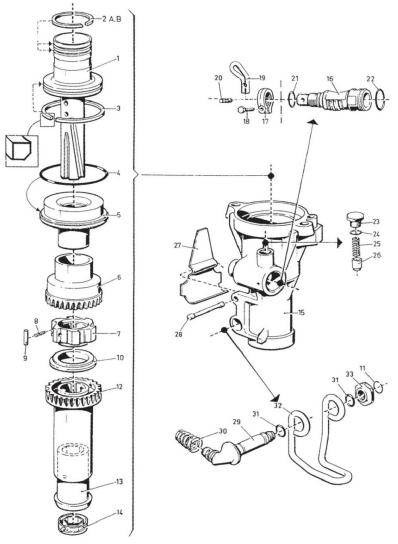
| Fig.No. | Qty | Description |
| 1 | 1 | Hammer piston |
| 2 | 1 | Piston ring set |
| 2A | 1 | Piston ring |
| 2B | 1 | Piston ring |
| 3 | 1 | Piston ring |
| 4 | 1 | O-ring |
| 5 | 1 | Hammer piston guide |
| 6 | 1 | Ratchet housing |
| 7 | 1 | Ratchet wheel assy |
| 8 | 6 | Spring |
| 9 | 6 | Roller |
| 10 | 1 | Spacer |
| 11 | 1 | Lock ring |
| 12 | 1 | Rotating sleeve |
| 13 | Collet assy | |
| 14 | 1 | Gasket |
| 15 | 1 | Drill chuck assy |
| 16 | 1 | Operating shaft |
| 17 | 1 | Locking nut |
| 18 | 1 | Screw |
| 19 | 1 | Lever |
| 20 | 1 | Pin |
| 21 | 1 | O-ring |
| 22 | 1 | 0-ring |
| 23 | 1 | Spring housing |
| 24 | 1 | O-ring |
| 25 | 1 | Spring |
| 26 | 1 | Plunger |
| 27 | 1 | Yoke spring |
| 28 | 1 | Lock pin |
| 29 | 1 | Yoke bolt assy |
| 30 | 1 | Spring |
| 31 | 2 | O-ring |
| 32 | 1 | Drill yoke |
| 33 | 1 | Drill yoke nut |
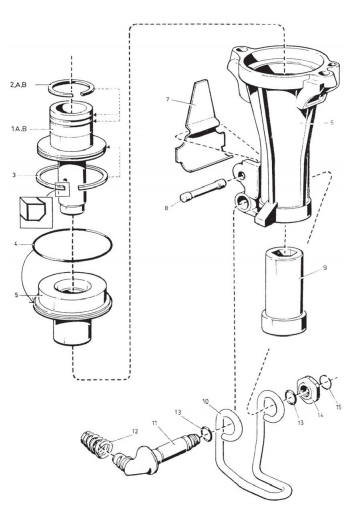
| Fig.No. | Qty | Description |
| 1 | 1 | Hammer piston |
| 2 | 1 | Piston ring set |
| 2A | 1 | Piston ring |
| 2B | 1 | Piston ring |
| 3 | 1 | Piston ring |
| 4 | 1 | O-ring |
| 5 | 1 | Hammer piston guide |
| 6 | 1 | Drill chuckassy |
| 7 | 1 | Yoke spring |
| 8 | 1 | Lock pin |
| 9 | 1 | Rotating sleeve |
| 10 | 1 | Drill yoke |
| 11 | 1 | Yoke bolt assy |
| 12 | 1 | Spring |
| 13 | 2 | O-ring |
| 14 | 1 | Drill yoke nut |
| 15 | 1 | Lock ring |
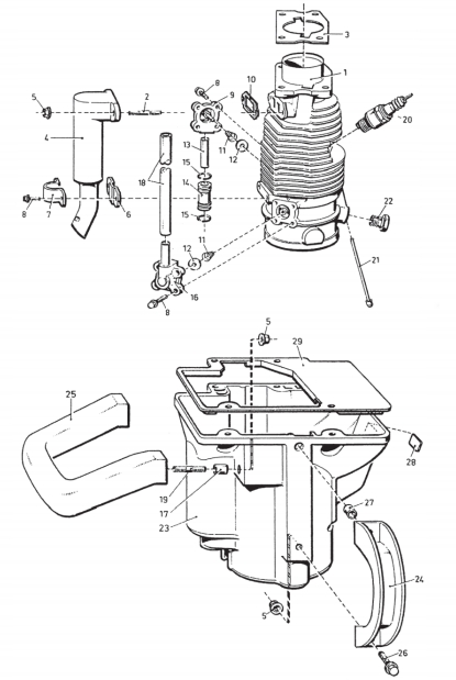
| Fig.No. | Qty | Description |
| 1 | 1 | Cylinder |
| 2 | 2 | Stud bolt |
| 3 | 1 | Gasket |
| 4 | 1 | Exhaust pipe |
| 5 | 6 | Nut |
| 6 | 1 | Washer |
| 7 | 1 | Clip |
| 8 | 10 | Screw |
| 9 | 1 | Blow valve seat |
| 10 | 1 | Gasket |
| 11 | 2 | Spring |
| 12 | 2 | Valve washer |
| 13 | 1 | Tube |
| 14 | 1 | Rubber hose |
| 15 | 2 | Lock ring |
| 16 | 1 | Intake valve seat |
| 17 | 2 | Bushing |
| 18 | 1 | Suction duct |
| 19 | 2 | Screw |
| 20 | 1 | Spark plug |
| 21 | 1 | Cleaning needle |
| 22 | Inlet valve | |
| 23 | 1 | Shield |
| 24 | 1 | Handle assy |
| 25 | 1 | Side handle |
| 26 | 2 | Bolt |
| 27 | 1 | Bushing |
| 28 | 1 | Label |
| 29 | 1 | Gasket |
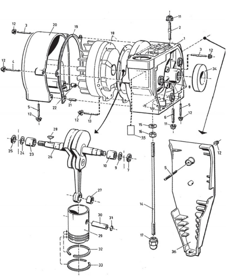
| Fig.No. | Qty | Description |
| 1 | 1 | Crank case assy |
| 2 | 3 | Stud |
| 3 | 4 | Stud |
| 4 | 1 | Stud |
| 5 | 4 | Stud |
| 6 | 4 | Stud |
| 7 | 1 | Retainer ring |
| 8 | 3 | Rubber cushior |
| 9 | 1 | Spacer |
| 10 | 1 | Needle bearing |
| 11 | 7 | Nut |
| 12 | 19 | Nut |
| 13 | 10 | Stud bolt |
| 14 | 2 | Draw bolt |
| 15 | 2 | Spring washer |
| 16 | 2 | Nut |
| 17 | 1 | Cap nut |
| 18 | 1 | Flywheel and Magneto classis parts |
| 19 | 1 | Gasket |
| 20 | 1 | Crankcase cover |
| 21 | 1 | Pin |
| 22 | 1 | Bushing |
| 23 | 1 | Needle bearing |
| 24 | 1 | Spacer |
| 25 | 1 | Retainer ring |
| 26 | 1 | Crank shaft assy |
| 27 | 1 | Needle bearing |
| 28 | 1 | Key |
| 29 | 1 | Engine piston set |
| 30 | 1 | Gudgeon pin |
| 31 | 2 | L ock ring |
| 32 | 2 | Piston ring |
| 33 | 1 | Piston ring |
| 35 | 1 | Plate |
| 36 | 1 | Wearing plate |
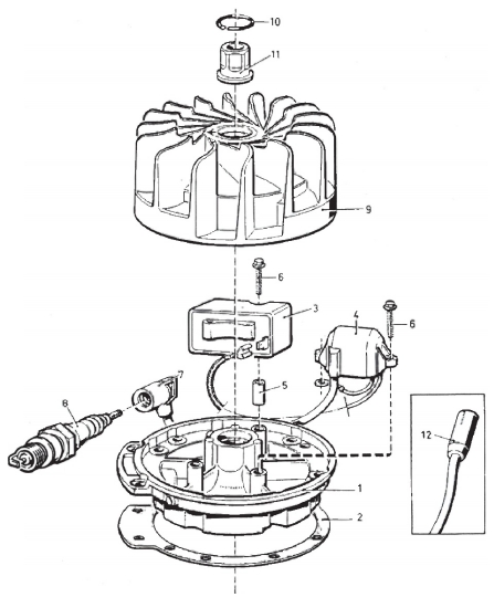
| Fig.No. | Qty | Description |
| 1 | 1 | Magneto chassis |
| 2 | 1 | Gasket |
| 3 | 1 | Electronic unit |
| 4 | 1 | Induction coil set |
| 5 | 1 | Bushing |
| 6 | 4 | Bolt |
| 7 | 1 | Cable terminal |
| 8 | 1 | Spark plug |
| 9 | 1 | Flywheel assy |
| 10 | 1 | Lock ring |
| 11 | 1 | Nut |
| 12 | 1 | Ignition cable |
| Fig.No. | Qty | Description |
| 1 | 1 | Clutch body |
| 2 | 4 | Ball |
| 3 | 1 | Snap ring |
| 4 | 1 | Stop screw |
| 5 | 1 | Rubber plug |
| 6 | 1 | Starter pulley |
| 7 | 1 | Needle bearing |
| 8 | 1 | Starter rope set |
| 9 | 1 | Starter handle |
| 10 | 1 | Rope bracket |
| 11 | 1 | Starter covei |
| 12 | 1 | Gasket |
| 13 | 1 | Starter spring |
| 14 | 1 | Fuel tank assy |
| 15 | Fuel tube | |
| 16 | 1 | Fuel filter |
| 17 | 1 | Tank cap |
| 20 | 1 | O-ring |
| 21 | 1 | Fuel tank cover |
| 22 | 1 | Guide rope piles |
| 23 | 15 | Stud |
| 24 | 2 | Pin |
| 25 | 1 | Stud bolt |
| 26 | 6 | Nut |
| Fig.No. | Qty | Description |
| 1 | 1 | Control |
| 2 | 1 | Pin |
| 3 | 4 | Screw |
| 4 | 1 | Nut |
| 5 | 1 | Wing nut |
| 6 | 1 | Spring |
| 7 | 1 | Retainer cup |
| 8 | 1 | 0-ring |
| 9 | 1 | Fuel needle assy |
| 10 | 1 | Fuel valve seat |
| 11 | 1 | O-ring |
| 12 | 1 | Nozzle,lower |
| 13 | 1 | Adjusting screw |
| 14 | 1 | Nut |
| 15 | 1 | Throttle set |
| 16 | 1 | Nut |
| 17 | 1 | Spring washer |
| 18 | 1 | Throttle control |
| 19 | 1 | Spring |
| 20 | 1 | Spring seat |
| 21 | 1 | Retaining ring |
| 22 | 1 | Throttle seat |
| 23 | 2 | O-ring |
| 25 | 2 | Leaf valve |
| 26 | 2 | Support |
| 27 | 4 | Spring washer |
| 28 | 1 | Stud |
| 29 | 1 | Lock clip |
| 30 | 2 | Valve sheet |
| 31 | 2 | Handle sleeve |
| 32 | 1 | Handle assy |
| 33 | 1 | Filter housing |
| 34 | 2 | O-ring |
| 35b | 1 | Filter element |
| 36 | 1 | Gasket |
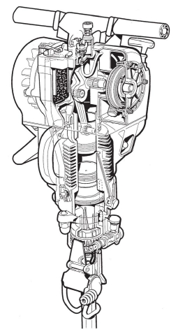
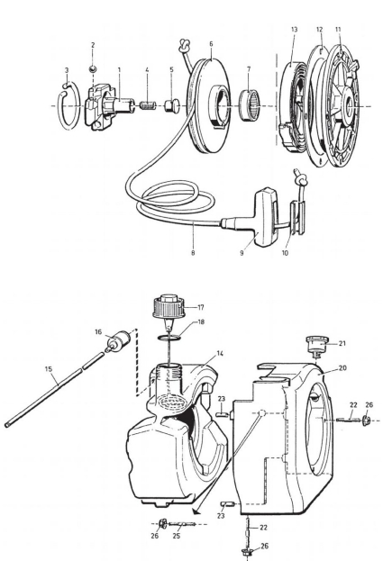
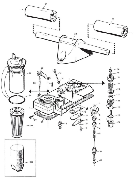
YN27C rock drill machine CONSTRUCTION
1.Engine:The engine is a hand operated single cylinder and two stroke petrol engine with air cooling,reflux air conversion,no contact ignition,and no floating-type carburetor.It is composed of control parts,starter parts,oil tank parts,flywheel parts,crankshaft,connecting rod,crankshaft case parts,shield parts,magneto parts,piston parts and cylinder parts.
2.Air compressor:The engine piston and hammer piston are mounted separately in the upper and lower place of the cylinder.These two pistons move up and down synchronously.The hammer piston and the bigger bore of the cylinder form a compression chamber,Which together with air inlet and outlet valves and ventilator valves,form the air compressor.It is composed of hammer piston parts and cylinder parts.
3.Rock drill:It is composed of hammer piston parts,rotation mechanism parts and drill chuck parts.
Lubrication and Cooling Action
Fuel used by the drill is 12:1,that is ,a mixed oil in the proportion 12 parts of gasoline to 1 part of lubricating oil.In operation,mixed oil enters into the crankshaft in fog to lubricate all parts of the crankshaft and the cylinder.During burning,gasoline burns,most of lubricating oil flow into all touching parts through the cylinder space to make them get complete lubrication.
The cylinder of engine is cooled by wind from the flywheel through the surface of emitting heat plates.
YN27·YN27C Operation
(1)Preparation before starting:
Preparing with mixed oil,drill rod,bit,funnel with filter net,some service tools and spark plug,etc.The ratio of mixed oil is 12:1.When the temperature is high or the quality of the lubricating oil is different,it can be adjusted to 6:1 to 10:1 as appropriate.
1.Gasoline:Use gasoline of 93#or 95#.
2.Lubricating oil:Use two-stroke gasoline engine lubricating oil or automotive lubricant,or low-condensation lubricant at lower temperature.
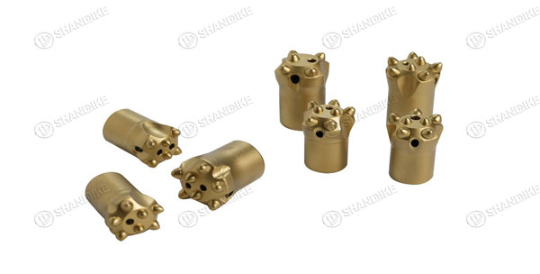
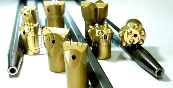
3.Length of dill rods and diameter of the carbide percussive drillbit:When drilling,a group of drill rod length with different size should be prepared in order to operate
conveniently and safely.They are 0.6m,1.1m,1.6m,2.0m,2.6m,3.0m,selecting them according to the depth of hole.In operating,o.6 is used to drill at first,then 1.1m instead of smaller one(Fig.1),then they are easy to choose and can work normally.
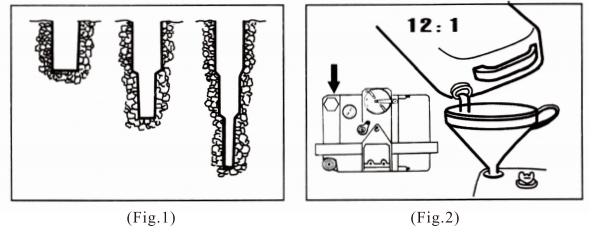
1、Erect the machine to support the handle of the control body ,and fill fuel into the gasoline tank.(Fig.2)
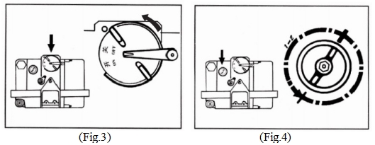
2.Close the air filter.(Fig.3)
3.Rotate the wing nut of fuel valve in counter clockwise one cycle or two to open it.(Fig.4)
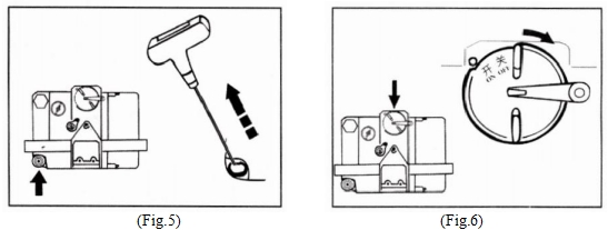
4.Pull the starter wire rope slowly for several times to let the mixed oil into the cylinder.When combustible gas in the cylinder burns,stop pulling.(Fig.5)
5.0pen the air filter.(Fig.6)
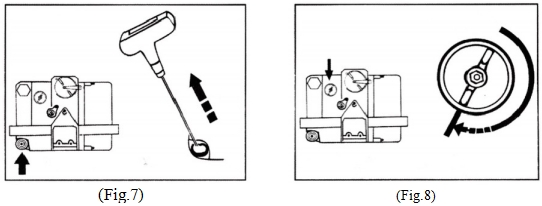
6.Pull the starter wire rope rapidly and powerfully to start.(Fig.7)After that the machine runs idly for several minutes in order to heat it,then turn the wing nut of fuel valve clockwise ,its rotating speed rises gradually.If abnormal sound with fog in the exhaust pipe,that means fuel supply is not enough.Right now,please turn the wing nut of the fuel valve in a counter clockwise direction and increase the amount of fuel supply.
7.Attention points for starting:
Mixed oil entering into the cylinder being too much or insufficient will be adverse to the starting of the engine.The operator is asked to make a correct judgement for the amount of the mixed oil in the cylinder.The method is to observe the state if a jet of fuel emerges from the exhaust pipe.If poor,please make the wing nut of fuel valve rotate in counter clockwise direction,open fuel valve full.Pull wire rope until combustible gas enter the cylinder burns and the engine be started.If a jet offuel emerges from the exhaust pipe,that means the fuel supply is too much,please make the wing nut of fuel valve rotate in clockwise direction and pull the starter wirerope for several times until it is operating then adjust the wing nut of the fuel valve in a appropriate position.(Fig.8)
(3)Drilling
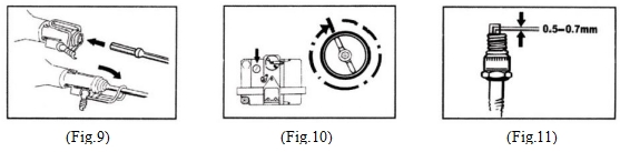
1.Fitting rod:Press the throttle valve with thumb to make the machine operate with lower speed ,then insert the shortest drills rod into the rotating sleeve.Snap down the yoke so that bit will notjump out.(Fig.9)
2.Start to drilling:Select an appropriate position.Slow down the rotating speed of the machine,use a foot to guide bit for facilitating the make hole.
3.Drilling hole:Release the throttle valve ,let the machine run at full speed.During operation,add appropriate pressure so that no jumping occurs to the machine.If the rotating speed of the machine is too low,adjust the fuel valve to raise its speed.
(4)Changing of rod
(4)Changing of rod Changing of rod ,press the throttle valve to reduce its rotating speed Snap up the yoke by foot,take out the bit and replace another one.Snap down the yoke and then accelerate the machine to full speed.
(5)Stopping:
Stop to work for short time,only press the throttle valve ,or close the air filter.Stop to work a long time,the fuel valve should be closed.(Fig.10)to avoid the too much oil enters into the cylinder.
(6)Hammering:
If digging,breaking,splitting or ramming:
1.To YN27 dismantle the rotating sleeve and mount the notch of the hammer sleeve alingning with the round pin in the drill chuck cover,and dismante the vetilating pipe between the cylinder and the drill chuck cover assy,then all hammering operations are able to be carried out.
2.To YN-27C you can operate in(Fig .12a)manner.
(7)Attention points for operation:
1.Fuel filling:only after the machine is stopped.
2.If the machine misfires,make an inspection.Don’t pull the starter wire rope vigorously to avoid damage to the Parts.
3.During operation ,don’t press the machine by human body to avoid to valid accidents when a bit breaks
4.When a bit is blocked ,don’t move it directly with the machine.
5.At the initial use of a new machine ,the throttle valve is not to be regulated high.Only after the machine is well mastered ,its speed can be regulated higher.
6.Working in terribly hot area,be cautious that the operation period is not too long.When the temperature of the machine is too high,a short stop is necessary till it gets cool.
7.To avoid corrosion,the machine should be stored at dry places.
Maintenance,Inspection and Adjustment
(1)To observe strictly the maintenance of the machine tool can not only ensure reliable running of machine,but also prolong its service life.
1.Before filling into oil tank,mixed oil must be filtered.
2.After starting,the machine tool should beatitude without any loads for 2-3 minutes to lubricate all sides in order to reduce trouble and prolong its life.
3.Everyday,operating 4 hour,take out the filter and wash itin gasoline.
4.Every week,outer of the machine and entitling heat plate of cylinder should be cleaned to send out heat.
Diagram of Air filter
5.When the machine is running,the deposited carbon is easily formed in the gas duet and on the other parts.Especially the bevel gas duct in cylinder must be assured of its free flow.When cleaning the bevel gas duct, switch down the inlet valve,take out cleaning needle and wipe out the deposited carbon in the bevel gas duct by the needle.(Fig.12)The inlet valve should also be kept lean.Several holes in the valves should be ensured free
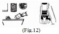
passage to allow free motion of the steel ball.
6.When running of the machine is abnormal make an overall inspection of engine or make carbon cleaning ,to wipe out carbon accumulated piston ring ,engine piston and impact piston ,exhaust hole in cylinder wall and spark gap.Dirt on the flywheel and magneto should also be taken away.
(2)Attention points for Inspection:
1.Be sure that clearance between spark gap electrodes should be 0.5-0.7mm and constantly clean off carbon and dirties to avoid circuit break and reduction of ignition.(Fig.11)
2.Be sure that the clearance between the steel ball of inlet valve and round pin. 3.Be sure that seal of the check valve plate at the bottom of control body.
4.Be careful whether the angle of ignition is changed.The arrow of flywheel should be aligned with the sign on the crankshaft.
Disassembling and assembling
The machine must be assembled correctly,strictly sealed and perfect cleanness.After a period of service,the machine needs cleaning and repairing,so disassembling and assembling are of a common occurrence.The following cautions should be followed in disassembling and assume bluing:
1.Disassembling and assembling should be done according to procedure.The parts,especially the piston tings,are to be mounted on their original positions.No errors and missing are allowed.
2.All the parts need to be washed in kerosene or gasoline and applied a layer of lubrication oil.In assembling,drive tight all the screws nuts and spark plug.Before trial running,pull the starter wire rope slightly for several times,to see if it is rotating freely,then start the machine.
3.If the machine need an overall disassemble it according to the following procedure.For assembling,do it reversibly:

In partial repair,do not disassemble the parts,which need no repairing.Try by every means to disassemble only the parts wanting to be repaired.
4.In disassembling starter parts,take off the starter spring,Starter wire pulley and starter cover together,be careful that spring breaks.The connection between clutch and crankshaft is left threaded,disassemble it in clockwise.And the starter wire rope should be mount in the wire pulley slot according to the arrow on starter cover.
5.In assembling the torque mechanism parts,be sure that the straight and drift slots on the impact piston lever are correctly in mesh with impact piston lever are correctly in mesh with inner keys of upper rachet and rotating sleeve.
6.Be very careful in disassembling piston ring to avoid breaking.
7.In disassembling the engine piston,a notch on the piston should be faced to the hole of spark plug.
8.Connecting crankshaft case.Cylinder and drill chuck cover.Two long screw levers should be driven tight in interchangeably to ensure the uniform pulling force,but not too tight.
Trouble shooting
| Fault | Cause | Remedy |
| 1.The engine is difficult to star | 1.Fuel system:(1).Clogging or poor sealing of fuel passages(2).Clogging of gasoline filter.(3).Use of a wrong brand of gasoline,over flow fuel or water in the fuel.(4).Poor sealing of the check valve plate on the control body.(5).Overflow mixed fuel in cylinder 2 Flectric system(1).Irregular gap between the spark plug electrodes,and oil conation,accumulated carbon on its surfaceorloose fitting of the plug core.(2).Shifting of the flywheel from its normal position(Wrong angle forignition) 3.Pneumatic system:(1).Low ratio of compression:a.Carbon deposition in or wear the cylinder.Engine positon ring.b.Clogging of the bevel gas duct in cylinderc.Irregular clearance of the steel ball in the inlet valve.(2).Air in sufficient supply:Carbon deposition in the outlet on cylinder and the connection pipe of the Silencer. | Take out of needle valve,blow thefuel hole of oil tank and block it witha hand,then shave it to make astream of oil sprays from the hole. Disassemble it,inspect and clean it Choose or blend the fuel by theregulations.Disassemble it and adjust it.Close fuels door,disassemble inletValve,pull starter wire rope for several times,take away overflow fuel. Adjust the gap by the regulationclear away carbon or oil or replace the plug with a new oneAlign the arrow on flywheel with the sign on the crankshaft. Clean or replace it.Clean away carbon in time. Adjust the steel ball clearance between 0.5-0.7mm Clean itin time. |
| Fault | Cause | Remedy | |
| 2.The engine worksinefficiently. | 1.Unfitting fuel door or clogging of fuel passage.2.Carbon deposition in the bevel gas duct,inlet valve,outlet valve and piston ring. 1.Clogging in the center hole of | Adjust it. Clean it in time. Clean it | |
| 3.Poor removal of cuttings | drillrod.2.Damage of hexagonal seal ring. 3.Damage or clogging of inlet and outlet valve.4.1rregular size and shape of tool shank. | Replace itReplace them. Replace it. | |
| 4 Poor rotation of tool shank. | 1.Damage of upper ratchet or olive ring.2.Excessive wears of keys of impact piston rod,Upper ratchet,Rotatingsleeve and other relevant parts.3.Running inefficient of engine. | Replace Replace See the | it. them. above. |
| 1.Seizer of the impact piston and | Eliminating the case and make | ||
| 5.The engine races. | drill rod.2.Changing of the flywheel sing. | rotation sleeve run freely. Adjust it and align it with the sign of crankshaft. | |
| 6.Abrupt stop of the machine | 1.Clogging of the hole in oil tankcap.2.Wrong with electric of fuel system3.Carbon deposition in the machine or excessive temperature | Clean it. See the above.Give it a complete overhaul. | |